Hey, Wes is posting code again!
I'm back, with a (tiny) vengeance. I'm working on a brand new system at work, where we have a bunch of sense lines we have to pay attention to, mostly to decide if we're allowed to transmit or not. The CPU module we've chosen doesn't have nearly enough digital I/O lines to support all of these, so I went searching for a cheap, fast enough, and reliable enough way to hang more digital I/Os on the board we're making.
I looked at some Mini PCIe designs, which tend to be fairly expensive (for what you get) and also require a Mini PCIe connector, and we don't like connectors. This thing is going to live outside the pressure shell on these aircraft, so it needs to be able to work at 55,000 feet, where it is very cold.
Once I started looking carefully at the designs, I noticed that the cheaper ones were not using the PCIe lane on the Mini PCIe connector, they were use the USB 2.0 lane. Ah hah! A quick search for USB to SPI bus interfaces led me to the FTDI FT4222 chip. More about this in another post. From there, I went looking for SPI based Digital I/Os, and found the MCP23S17 from MicroChip. MicroChip is a good company to work with; they're very open about datasheets for their products, errata notices, and they provide eval units and even sample chips. So we got a couple of samples of the 23S17 in DIP form factor to make them easy to breadboard.
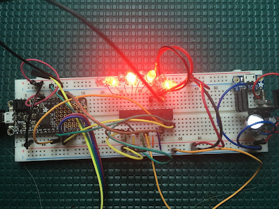
The FT4222 eval hasn't arrived yet, so I stuffed one of the 23S17s into a breadboard with my favorite microcontroller, my trusty and well-used Adafruit Feather M0. This on specifically is the Basic Proto version, but I have several of the ones with the RFM69 radios too.
After wiring the chip to the SPI bus, I started plunking around. Ultimately what we want to do is use one of these for all the "discrete" sense lines coming into the ModMan, even the ones that go to other units inside the box, because we're responsible for logging the state of all these inputs. So we'll condition all those signals, tee them where needed, and deliver them to my little I/O maven for sensing.
The 23S17 (and it's I2C brother the 23017) offer an interrupt-on-change mode; if any of the configured inputs changes state, the chip will read the port into an internal register and issue an interrupt. This is perfect for our needs, since we only need to log these when they change. So I wanted to explore getting interrupt-on-change to work. Here's my solution. I should create a diagram of the circuit in Fritzing and add that, but for now a photo will have to suffice.
The code is simple. I used the SPI hardware on the M0, but created all my own register definitions and such, so you can see exactly what I'm doing to the chip.
This is the interrupt handler for the change interrupt. It notes to the loop code that an interrupt has been received, grabs the saved contents of the input port from the "capture" port, and does some Arduino-ish housekeeping to keep itself going.
Arduino programs start by calling the setup() function once.
Here we open the serial console port and wait for it to connect, then setup the 23S17 chip with a series of register writes.
Arduino programs continue by calling the loop() function continuously, once the setup() function has returned.
This is fairly trivial, in the general case we just delay() for 50 milliseconds. If we did catch an interrupt, we invert the value and write it to Port A, which has 8 LEDs attached, then print the new value on the console.
So that's it! When I get the FT4222 board, the first task will be to duplicate this through the USB interface, from Linux. That will be time for another post.
I couldn't find any simple, clear examples of using the interrupt on capture mode, so I made my own. I should probably gist this too.
I'm back, with a (tiny) vengeance. I'm working on a brand new system at work, where we have a bunch of sense lines we have to pay attention to, mostly to decide if we're allowed to transmit or not. The CPU module we've chosen doesn't have nearly enough digital I/O lines to support all of these, so I went searching for a cheap, fast enough, and reliable enough way to hang more digital I/Os on the board we're making.
I looked at some Mini PCIe designs, which tend to be fairly expensive (for what you get) and also require a Mini PCIe connector, and we don't like connectors. This thing is going to live outside the pressure shell on these aircraft, so it needs to be able to work at 55,000 feet, where it is very cold.
Once I started looking carefully at the designs, I noticed that the cheaper ones were not using the PCIe lane on the Mini PCIe connector, they were use the USB 2.0 lane. Ah hah! A quick search for USB to SPI bus interfaces led me to the FTDI FT4222 chip. More about this in another post. From there, I went looking for SPI based Digital I/Os, and found the MCP23S17 from MicroChip. MicroChip is a good company to work with; they're very open about datasheets for their products, errata notices, and they provide eval units and even sample chips. So we got a couple of samples of the 23S17 in DIP form factor to make them easy to breadboard.
The FT4222 eval hasn't arrived yet, so I stuffed one of the 23S17s into a breadboard with my favorite microcontroller, my trusty and well-used Adafruit Feather M0. This on specifically is the Basic Proto version, but I have several of the ones with the RFM69 radios too.
After wiring the chip to the SPI bus, I started plunking around. Ultimately what we want to do is use one of these for all the "discrete" sense lines coming into the ModMan, even the ones that go to other units inside the box, because we're responsible for logging the state of all these inputs. So we'll condition all those signals, tee them where needed, and deliver them to my little I/O maven for sensing.
The 23S17 (and it's I2C brother the 23017) offer an interrupt-on-change mode; if any of the configured inputs changes state, the chip will read the port into an internal register and issue an interrupt. This is perfect for our needs, since we only need to log these when they change. So I wanted to explore getting interrupt-on-change to work. Here's my solution. I should create a diagram of the circuit in Fritzing and add that, but for now a photo will have to suffice.
The code is simple. I used the SPI hardware on the M0, but created all my own register definitions and such, so you can see exactly what I'm doing to the chip.
#include <SPI.h>

const uint8_t ADDR = 0x20;      //MCP23S17 address, all 3 ADDR pins are grounded
const uint8_t OPCODE_READ  = (ADDR << 1 | 0x01); //MCP23S17 read command

// 23S17 register addresses

#define IODIRA   0x00
#define IODIRB   0x01
#define IPOLA    0x02
#define IPOLB    0x03
#define GPINTENA 0x04
#define GPINTENB 0x05
#define DEFVALA  0x06
#define DEFVALB  0x07
#define INTCONA  0x08
#define INTCONB  0x09
#define IOCONA   0x0a
#define IOCONB   0x0b
#define GPPUA    0x0c
#define GPPUB    0x0d
#define INTFA    0x0e
#define INTFB    0x0f
#define INTCAPA  0x10
#define INTCAPB  0x11
#define GPIOA    0x12
#define GPIOB    0x13
#define OLATA    0x14
#define OLATB    0x15

// MCP supports cascaded devices on the same SPI bus & CS
// We'll be device 0.

const uint8_t PORT_EXPANDER_ADDRESS = 0;
const uint8_t SLAVE_CONTROL_BYTE = 0b1000000 | (PORT_EXPANDER_ADDRESS << 1);

// Feather M0 setup

#define CS 5  // Chip select on pin 5
#define INT 6 // Input change interrupt on pin 6

SPISettings spiSettings(SPI_CLOCK_DIV8, MSBFIRST, SPI_MODE0);


// Utility functions to talk to the 23S17.
// There are C++ libraries that wrap this, but meh.

void writeByte(uint8_t reg, uint8_t data)
{
  digitalWrite(CS, LOW);

  SPI.transfer(SLAVE_CONTROL_BYTE);
  SPI.transfer(reg);
  SPI.transfer(data);

  digitalWrite(CS, HIGH);
}

uint8_t readByte(uint8_t reg)
{
  digitalWrite(CS, LOW);

  SPI.transfer(SLAVE_CONTROL_BYTE | 1);
  SPI.transfer(reg);
  uint8_t data = SPI.transfer(0);

  digitalWrite(CS, HIGH);
  return data;
}
This is the interrupt handler for the change interrupt. It notes to the loop code that an interrupt has been received, grabs the saved contents of the input port from the "capture" port, and does some Arduino-ish housekeeping to keep itself going.
// Interrupt on change handler

volatile bool gotOne = true;
volatile uint8_t capture = 0;

void changeInt()
{
  // Read the change FIFO here...
  gotOne = true;

  SPI.beginTransaction(spiSettings);
    capture = readByte(INTCAPB);
  SPI.endTransaction();

  // Reattach the interrupt (is this necessary?)
  attachInterrupt(INT, changeInt, LOW);
}
Arduino programs start by calling the setup() function once.
Here we open the serial console port and wait for it to connect, then setup the 23S17 chip with a series of register writes.
void setup()
{
  Serial.begin(9600);
  while (!Serial);

  pinMode(CS, OUTPUT);                //configure controller's Slave Select pin to output
  digitalWrite(CS, HIGH);             //disable Slave Select

  pinMode(INT, INPUT_PULLUP);         // configure pin 6 for interrupt-on-change
  attachInterrupt(INT, changeInt, LOW);

  // DIO configuration:
  SPI.begin();

  // configure Port A for output

  SPI.beginTransaction(spiSettings);
    writeByte(IODIRA, 0);             // All Port A pins are outputs
  SPI.endTransaction();

  // configure Port B for input, pullup, inverted, interrupt on change

  SPI.beginTransaction(spiSettings);
    writeByte(IODIRB, 0xff);          // All Port B pins are inputs
    writeByte(GPPUB, 0xff);           // All Port B pins are pulled up
    writeByte(IPOLB, 0xff);           // All Port B pins are inverted (GND = 1)
    writeByte(GPINTENB, 0xff);        // All Port B pins interrupt on change
    writeByte(INTCONB, 0);            // Interrupt on any change
    readByte(INTCAPB);                // Empty the Port B capture register
  SPI.endTransaction();

  // Merge interrupts even though we're only using one

  SPI.beginTransaction(spiSettings);
    writeByte(IOCONA, 0b01000000);             // Mirror Port A/B interrupts
    writeByte(IOCONB, 0b01000000);
  SPI.endTransaction();

  Serial.println("MCP23S17 port B->A inverter:");
}
Arduino programs continue by calling the loop() function continuously, once the setup() function has returned.
This is fairly trivial, in the general case we just delay() for 50 milliseconds. If we did catch an interrupt, we invert the value and write it to Port A, which has 8 LEDs attached, then print the new value on the console.
void loop()
{
  // This is totally not debounced.  We use the delay below to keep it from bouncing too much.
  if (gotOne)
  {
    gotOne = false;
    SPI.beginTransaction(spiSettings);
      writeByte(GPIOA, capture ^ 0xff);
    SPI.endTransaction();               //release the SPI bus
    Serial.print("Got one: ");
    Serial.println(capture, BIN);
  }

  delay(50);
}
So that's it! When I get the FT4222 board, the first task will be to duplicate this through the USB interface, from Linux. That will be time for another post.
I couldn't find any simple, clear examples of using the interrupt on capture mode, so I made my own. I should probably gist this too.

Comments
Post a Comment